
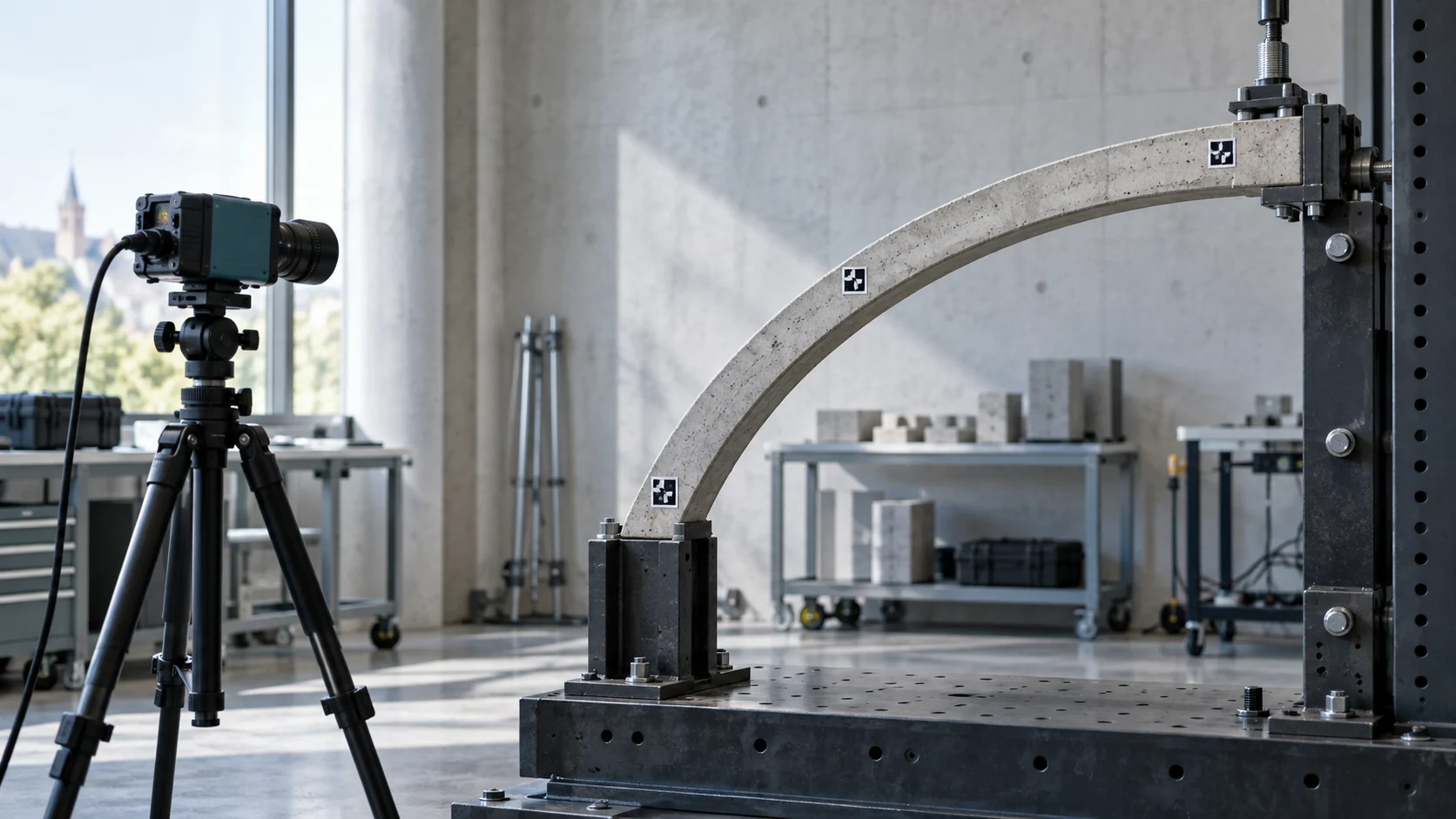
Problem
What needed to be understood or measured
Scaled structural tests need synchronized, non-contact measurements across multiple elements without a dense network of wired sensors.
My contribution
My contribution
I contributed to marker tracking and evaluation as a computer-vision co-author. The papers do not specify a finer per-author task split.
Experimental setup
Data and setup
DeepTag markers, calibrated camera geometry, PnP pose estimation, a 6-DoF motorized reference for characterization, and later cantilever-beam dynamic tests at 2 Hz and 3 Hz.
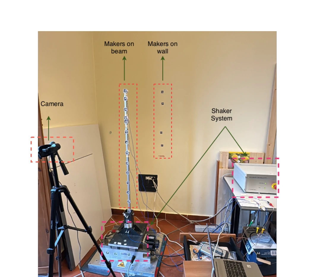 Open figure —
Full experimental setup for the preliminary structural dynamic test.
Preliminary Assessment of a Low-Cost DeepTag-Based Vision System, Fig. 2, p. 3.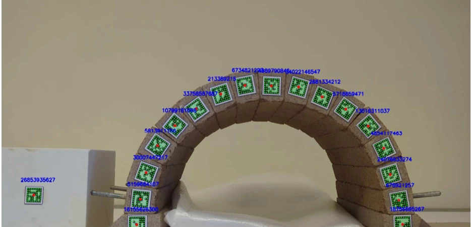 Open figure —
Scaled arch with tracked DeepTag markers.
Development and Evaluation of a Novel Marker-Based Tracking System, Fig. 5, p. 3.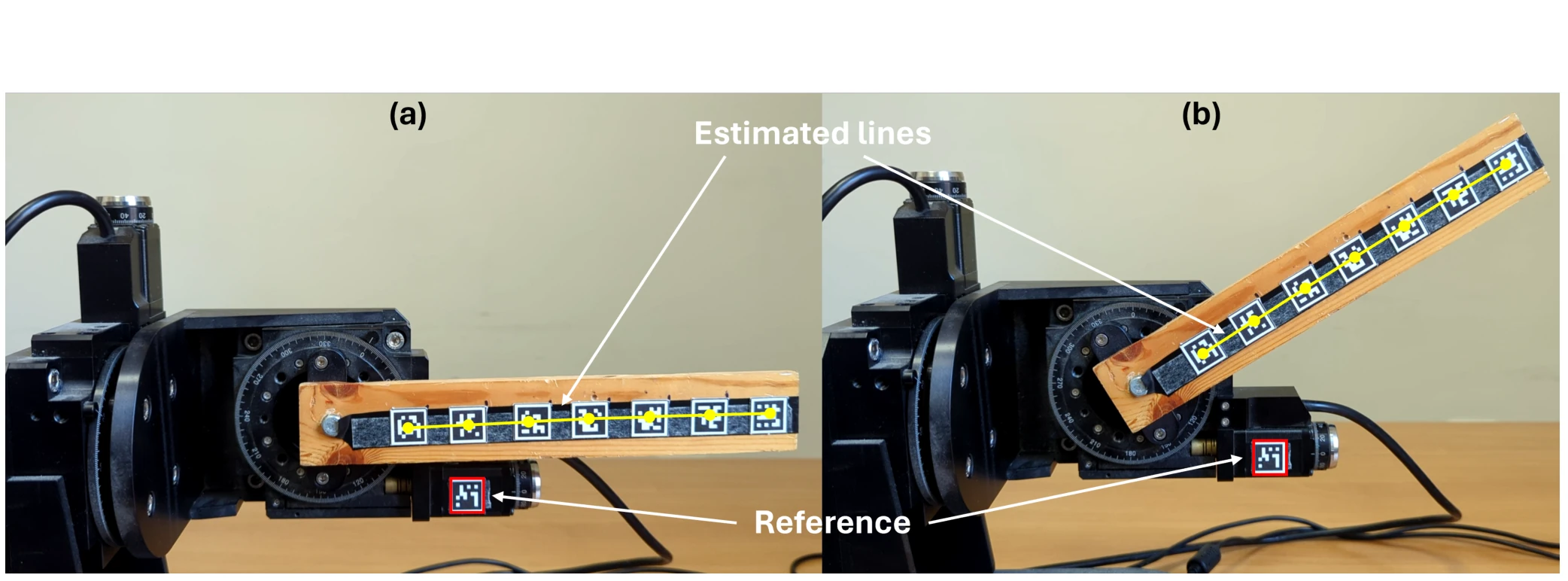 Open figure —
Motorized reference setup used for preliminary orientation characterization.
Low-Cost Marked Tracking Monitoring System, Fig. 1, p. 3.Method
From input to interpretable output
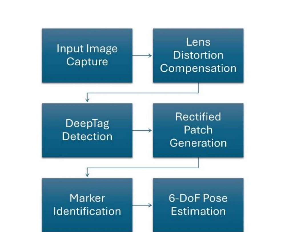
Detect marker regions, rectify each ROI, decode keypoints, map them back to the original frame, and estimate pose. Physical displacement is compared with a theoretical or controlled reference response.
 Open figure —
DeepTag 6-DoF pose-estimation workflow.
Development and Evaluation of a Novel Marker-Based Tracking System, Fig. 1, p. 2.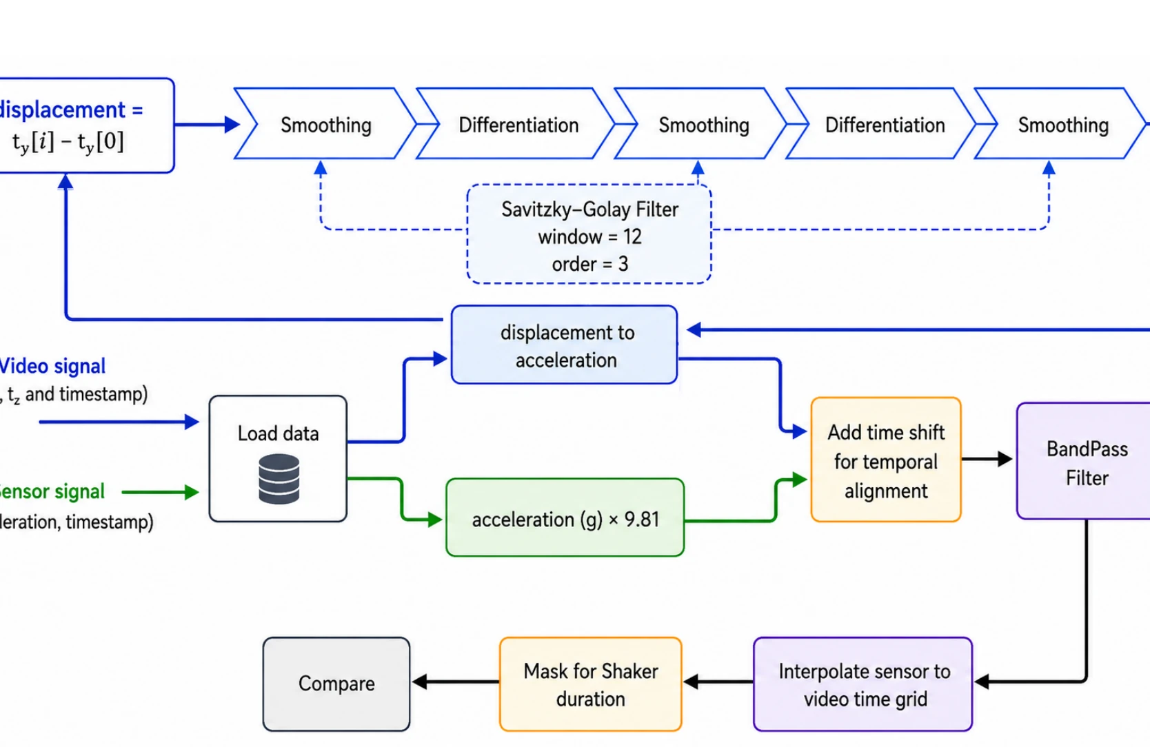 Open figure —
Pipeline used to align and compare vision-derived displacement with the reference sensor.
Preliminary Assessment of a Low-Cost DeepTag-Based Vision System, Fig. 1, p. 2.Results
Reported results
maximum expanded orientation uncertainty
k = 2; characterization study
maximum segment-distance IQR
repeatability study
beam displacement RMSE
preliminary 2 Hz and 3 Hz tests
 Open figure —
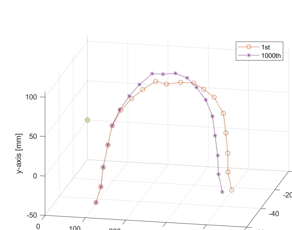
Tracked 3D arch geometry before and after the imposed support displacement.
Development and Evaluation of a Novel Marker-Based Tracking System, Fig. 6, p. 4.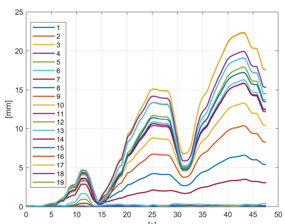 Open figure —
Displacement magnitudes for the 19 tracked masonry blocks.
Development and Evaluation of a Novel Marker-Based Tracking System, Fig. 7, p. 4.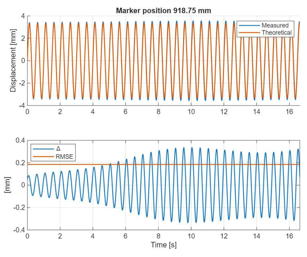 Open figure —
Measured versus theoretical displacement at 2 Hz, with the residual shown below.
A Low-Cost Vision-Based Monitoring System for Dynamic Testing of a Cantilever Beam, Fig. 4, p. 4.Validation & uncertainty
Reference and uncertainty checks
The marker study reports repeatability and expanded uncertainty under controlled motion. The later cantilever experiment compares vision-derived displacement with a reference response at two excitation frequencies.
 Open figure —
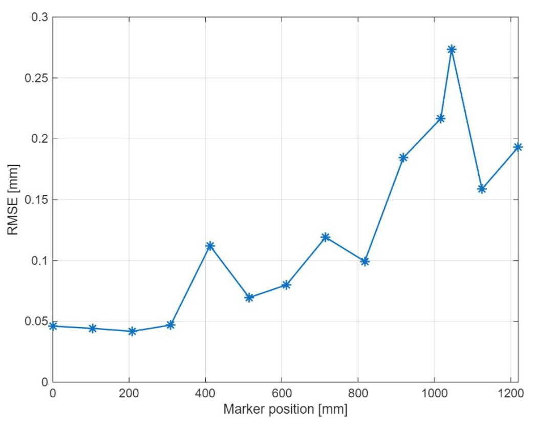
RMSE across marker locations for the 2 Hz test.
Cantilever-beam paper, Fig. 5, p. 4.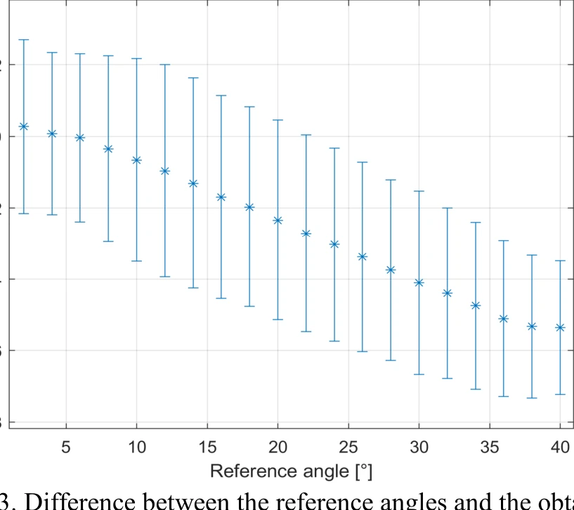 Open figure —
Orientation error and expanded uncertainty from the controlled reference motion.
Development and Evaluation of a Novel Marker-Based Tracking System, Fig. 3, p. 3.Limitations & failure modes
Operating limits and failure modes
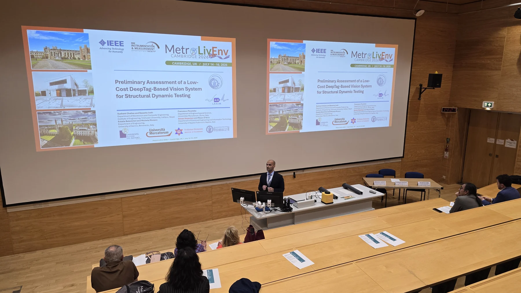
Presentation of the structural dynamic-testing study at Metrology for Living Environment 2026.
Conference photograph.Marker visibility, blur, oblique viewing angles, calibration drift, synchronization error, and out-of-plane motion can all degrade pose or displacement estimates.
The reported results belong to controlled characterization and preliminary laboratory tests. They do not establish field-scale bridge monitoring performance.
Technical stack
Tools selected for the measurement chain
- Python
- OpenCV
- DeepTag
- Camera calibration
- PnP
- Uncertainty analysis
Sources & project links
Papers and code
DeepTag characterization paper (ET 2024), masonry tracking paper (ET 2024), and cantilever-beam paper (MetroSustainability 2025).